Cannot Read Data With okPipeOut

Hello there,

I am trying to use the okPipeOut module to read out counter values and store them in a file on my PC. I am using a Vivado FIFO core to cross the clock boundary between my HDL clock (200MHz) and the USB clock (100MHz). I currently have the “epread” output from the okPipeOut module connected to my read enable signal on the FIFO. When I simulate my design I see that counter values are being stored in the FIFO and write acknowledge signals are toggling but no data is being read out of the FIFO. After looking closer I see the read clock signal toggling but the read enable signal that connects to epread never changes from zero.

Is there something I am missing as to why epread is not changing?

Here is some code on how I am connecting the FIFO and okPipeOut:
okPipeOut pipea0(
.okHE(okHE),
.okEH(okEH),
.ep_addr(8’ha0),
.ep_read(rd_en_connect), //Wire that connects the output read signal from okPipeOut to the rd_en on the FIFO
.ep_datain(dout) //FIFO output signal dout
);

fifo_generator_0 myfifo (
.wr_clk(clk), // Input clock signal used in the HDL code (200MHz)
.rd_clk(okClk), // Internal USB clock signal used for read clock (100MHz)
.din(count_out), // Output of the counter connecting to the input of the FIFO
.wr_en(wr_en), // Internally generated write enable signal
.rd_en(rd_en_connect),
.dout(dout), // FIFO output connecting to the input of okPipeOut
.full(full),
.empty(empty),
.wr_ack(),
.valid() /
);

Any help would be appreciated.

How are you calling ReadFromPipeOut from your FrontPanel program? Is pipea0 your only FrontPanel module? What device are you using?

All I have done so far is created an HDL module with a counter and then connected my FIFO, okHost, okTriggerIn and okPipeOut modules. I also created a GUI that has a reset button and PipeOut button. The reset button connects to my okTriggerIn module and the PipeOut button uses the okFilePipe feature to store my counter values in a file.

I have not used the ReadFromPipeOut feature that you are referencing which may be my problem. Could you please explain a little more on what that is? I am using the XEM7310MT-A200 device.

My overall goal is to read out counter values from my HDL module and store them in a file on my PC. I was under the impression that I only needed a GUI and HDL code to do this.

Here are the other FrontPanel modules that connect back to my counter:

okHost okHI(
.okUH(okUH),
.okHU(okHU),
.okUHU(okUHU),
.okAA(okAA),
.okClk(okClk),
.okHE(okHE),
.okEH(okEH)
);

okTriggerIn rtrig(
.okHE(okHE),
.ep_addr(8’h40),
.ep_clk(clk),
.ep_trigger(reset) // Connects to the reset in my counter
);

I can post my whole code if that would be more helpful. Sorry for the confusion, this is my first time using FrontPanel.

No worries. Yes, you are able to use the okFilePipe button. It looks like you are on the right track. Check out the DES sample in the Samples folder of the Opal Kelly install and copy how the PipeIn is instantiated in destop.v if you are confused. Double check your endpoints. If you are still stuck, you can post your whole code here.

I did what you said and looked at the DES sample to see how they are connecting the PipeIn and PipeOut modules. I also double checked my endpoints but I don’t see the issue.

When I run a behavioral simulation in Vivado I don’t see any change in my rd_en_connect wire which is connected to ep_read from the PipeOut module. This means that ep_read is never going high and signaling to the FIFO to read out the stored counter values.

Here is my complete code. The Pulse_counter module is using a counter to measure the width of an incoming pulse in_1. This is accomplished by counting how many clock cycles the signal is high and then multiplying by the period. The pulse measurement is stored in register count_out, written into the FIFO and then (ideally) read from the FIFO and stored in a file on my PC.

`timescale 1ns / 1ps

module Pulse_counter(
input in_1  ,                      // Input signal
input clk,                         // Internal clock signal on FPGA (200MHz)

input wire [4:0] okUH,	       // Input from Opal Kelly USB controller (from PC)
output wire [2:0] okHU,	       // Outputs to Opal Kelly USB Controller (to PC)
inout wire [31:0] okUHU,	   // Bidirectionals to USB Controller
inout wire okAA
);

    wire okClk;                 // Clock used by Opal Kelly USB controller
    wire [112:0] okHE;          // Opal Kelly module address and control bus
    wire [64:0] okEH;           // Outputs from the various OK modules back to the okHost core
    
    reg [15:0] counter;
    reg [15:0] count_out;       // Output of the counter, after multiplied by the period 
    wire rd_en_connect;
    reg wr_en;
    wire empty; 
    wire full; 
    wire [15:0] dout; 
    wire reset;                 // Counter reset signal
    
    reg in_1_del;
    wire in_1_ne = !in_1 & in_1_del;             // Negative edge of in_1 used to trigger the FIFO's write enable 


initial counter = 16'b0; 
initial wr_en = 1'b0;

fifo_generator_0 myfifo (
  .wr_clk(clk),         // Input clock signal used in the HDL code (200MHz)
  .rd_clk(okClk),       // Internal USB clock signal used for read clock (100MHz)
  .din(count_out),      // Output of the counter connecting to the input of the FIFO
  .wr_en(wr_en),        // Internally generated write enable signal
  .rd_en(rd_en_connect),    
  .dout(dout),          // FIFO output connecting to the input of okPipeOut
  .full(full),      
  .empty(empty),   
  .wr_ack(),        
  .valid()         
);


okHost okHI(
	.okUH(okUH),
	.okHU(okHU),
	.okUHU(okUHU),
	.okAA(okAA),
	.okClk(okClk),
	.okHE(okHE), 
	.okEH(okEH)
);

okTriggerIn rtrig( 
    .okHE(okHE), 
    .ep_addr(8'h40), 
    .ep_clk(clk),
    .ep_trigger(reset)       // Connects to the reset in my counter
);

okPipeOut pipea0(
     .okHE(okHE),
     .okEH(okEH), 
     .ep_addr(8'ha0),       
     .ep_read(rd_en_connect),      //Wire that connects the output read signal from okPipeOut to the rd_en on the FIFO
     .ep_datain(dout)              //FIFO output signal dout
);

always @(posedge clk) begin
    if (reset || counter==16'hFFFF) begin
        counter <= 16'b0 ;         // If reset is high reset the counter to 0
    end
    else if (in_1) begin
        counter <= counter + 1;    // As long as input is high keep counting
    end
    else if (in_1 == 16'b0) begin 
        if (counter !== 16'b0) begin    
            count_out <= 5*counter;     
        end
        counter <= 16'b0;          
    end
end

always @(posedge clk) begin
    if (reset) begin
        in_1_del <= 1'b0;        
    end else begin
        in_1_del <= in_1;        
    end
end

always @(posedge clk) begin
    if (reset || full) begin
        wr_en <= 1'b0;        
    end else begin
        wr_en <= in_1_ne;        
    end
end         
  
endmodule

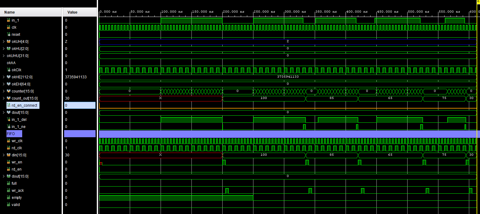
Here is my simulation result where you can see that rd_en_connect (orange) is not toggling so my FIFO data is not being read.